
The "2D | Story" calculation diagram type is used to create result diagrams via the building axis. This allows you to easily analyze the behavior of the entire building under static and dynamic effects.
You can use this diagram type, for example, to visualize the seismic force over the building height.

The Concrete Design add-on provides you with the option to perform the simplified fire resistance design according to EN 1992‑1‑2 for columns (Section 5.3.2) and beams (Section 5.6).
The following design checks are available for the simplified fire resistance design:
- Columns: Minimum cross-sectional dimensions for rectangular and circular sections according to Table 5.2a as well as Equation 5.7 for calculating time of fire exposure
- Beams: Minimum dimensions and center distances according to Table 5.5 and Table 5.6
You can determine the internal forces for the fire resistance design according to two methods.
- 1 Here, the internal forces of the accidental design situation are included directly into the design.
- 2 The internal forces of the design at normal temperature are reduced by the factor Eta,fi (ηfi), then used in the fire resistance design.
Furthermore, it is possible to modify the axis distance according to Eq. 5.5.

Would you like to create a cross-section from the import of a DXF file? It's very easy. You have the following options:
- Create elements automatically
- Use DXF template lines as centerlines of elements with a defined thickness
Do you select the option to create the elements automatically? In that case, the program creates the elements and the associated parts for you from the contour of the outline. It only creates the elements not exceeding a definable maximum thickness.
Your cross-section geometry is available as a centroidal axis model? Then use DXF template lines as centerlines of elements with a defined thickness. Defining a thickness that is assigned equally to all elements.
Do you miss the "Create elements automatically" and "Create elements on lines" functions? Don't worry, both are also available in the "Edit" menu under "Manipulation".
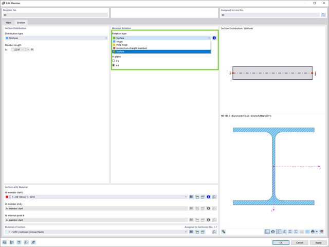
Easily define the rotation of a member in the direction of the local axes of a surface that is, for example, inclined in space.
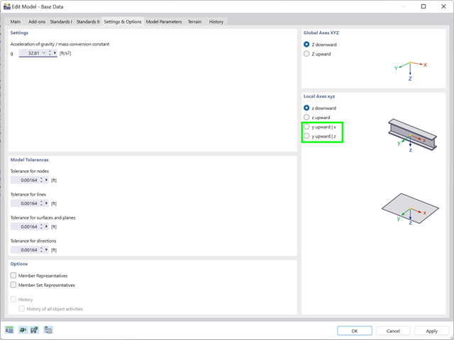
The improvements in the international context are not neglected either. A new local axis specification (y upwards) has been added for the Anglo-American region.

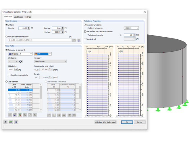
To model structures in RWIND Basic, you find a special application in RFEM and RSTAB. Here, you define the wind directions to be analyzed by means of related angular positions about the vertical model axis. At the same time, you define the elevation-dependent wind profile on the basis of a wind standard. In addition to these specifications, you can use the stored calculation parameters to determine your own load cases for a stationary calculation per each angular position.
As an alternative, you can also use the RWIND Basic program manually, without the interface application in RFEM or RSTAB. In this case, RWIND Basic models the structures and terrain environment directly from the imported VTP, STL, OBJ, and IFC files. You can define the height-dependent wind load and other fluid-mechanical data directly in RWIND Basic.

- Determination of longitudinal, shear, and torsional reinforcement
- Representation of minimum and compression reinforcement
- Determination of neutral axis depth, concrete and steel strains
- Design of member sections affected by bending about two axes
- Design of tapered members
- Design of RSECTION cross-sections (see this Product Feature)
- Determination of deformation in state II; for example, according to EN 1992‑1‑1, 7.4.3, and ACI 318‑19 24.2.3, Table 24.2.3.5
- Considering tension stiffening
- Considering creep and shrinkage
- Fatigue design according to EN 1992‑1‑1, Section 6.8 (see this Product Feature)
- Simplified fire resistance design according to EN 1992‑1‑2 for Columns (Section 5.3.2) and Beams (Section 5.6) (see this Product Feature)
- Seismic design according to EC 8 (see this Product Feature)
- Precise breakdown of reasons for failed design
- Design details of all design locations for better traceability of reinforcement determination
- Optional cross-section optimization
- Visualization of concrete section with reinforcement in 3D rendering
- Creation of 2D interaction diagrams; for example, M-N diagram
- Visualization of section resistance in 3D interaction diagram
- Output of moment-curvature diagram
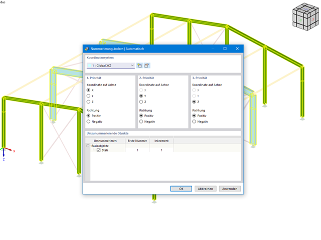
This feature helps you stay flexible in your planning. You can subsequently adjust the numbering of structural objects, such as nodes and members. In this case, it is possible to renumber the objects automatically in accordance with the selected priorities (axis directions).
Rely on the Dlubal programs even in windy matters. RFEM and RSTAB provide a special interface for exporting models (that is, structures defined by members and surfaces) to RWIND 2. There, the wind directions to be analyzed for your project are defined by means of related angular positions about the vertical model axis. Furthermore, the elevation-dependent wind profile and turbulence intensity profile are defined on the basis of a wind standard. These specifications result in specific load cases, depending on the angle. For this, the fluid parameters, turbulence model properties, and iteration parameters that are all stored globally are helpful. You can extend these load cases by partial editing in the RWIND 2 environment using terrain or environment models from STL vector graphics.
As an alternative, you can also run RWIND 2 manually and without the interface application in RFEM or RSTAB. In this case, the structures and terrain environment in the program are directly modeled by imported STL and VTP files. You can define the height-dependent wind load and other fluid-mechanical data directly in RWIND 2.
Due to its versatile applicability, RWIND 2 is always at your side to support you in your individual projects.
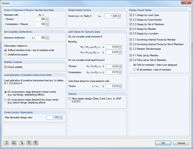
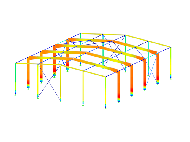
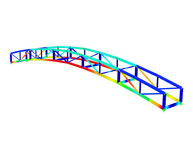
- Design of tension, compression, bending, shear, and combined internal forces
- Stability analysis for flexural buckling and lateral-torsional buckling
- Automatic determination of critical buckling loads and critical buckling moments for general load applications and support conditions by means of a special FEA program (eigenvalue analysis) integrated in the module
- Optional application of discrete lateral supports to beams
- Automatic cross-section classification
- Deformation analysis (serviceability)
- Cross-section optimization
- Wide range of cross-sections available, such as rolled I-sections, C-sections, rectangular hollow sections, angles, double angles (arrangement flange on flange), T-sections. Welded sections: I-shaped (symmetrical and asymmetrical about major axis), channel sections (symmetrical about major axis), rectangular hollow sections (symmetrical and asymmetrical about major axis), angles, round pipes, and round bars
- Clearly arranged result tables
- Detailed result documentation including references to design equations of the used standard
- Various filter and sorting options of results, including result lists by member, cross-sections, x-location, or by load case, load and result combination
- Result table of member slenderness and governing internal forces
- Parts list with weight and solid specifications
- Seamless integration in RFEM/RSTAB
- Metric and imperial units
- Design of tension, compression, bending, shear, and combined internal forces
- Stability analysis for flexural buckling and lateral-torsional buckling
- Automatic determination of critical buckling loads and critical buckling moments for general load applications and support conditions by means of a special FEA program (eigenvalue analysis) integrated in the module
- Optional application of discrete lateral supports to beams
- Automatic cross-section classification (Class 1 to 3)
- Deformation analysis (serviceability)
- Cross-section optimization
- Wide range of cross-sections available, such as rolled I-sections, C-sections, rectangular hollow sections, angles, double angles (arrangement flange on flange), T-sections. Welded sections: I-shaped (symmetrical and asymmetrical about major axis), channel sections (symmetrical about major axis), rectangular hollow sections (symmetrical and asymmetrical about major axis), angles, round pipes, and round bars
- Clearly arranged result tables
- Detailed result documentation including references to design equations of the used standard
- Various filter and sorting options of results, including result lists by member, cross-sections, x-location, or by load case, load and result combination
- Result table of member slenderness and governing internal forces
- Parts list with weight and solid specifications
- Seamless integration in RFEM/RSTAB
- Metric and imperial units
- Import of results from RSTAB
- Integrated material and cross-section library
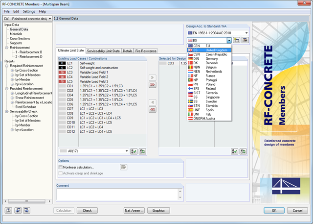
- The module extension EC2 for RSTAB enables design of reinforced concrete according to EN 1992-1-1 (Eurocode 2) and the following National Annexes:
-
 DIN EN 1992-1-1/NA/A1:2015-12 (Germany)
 -
 ÖNORM B 1992-1-1:2018-01 (Austria)
 -
 Belgium NBN EN 1992-1-1 ANB:2010 for design at normal temperature, and NBN EN 1992-1-2 ANB:2010 for fire resistance design (Belgium)
 -
 BDS EN 1992-1-1:2005/NA:2011 (Bulgaria)
 -
 EN 1992-1-1 DK NA:2013 (Denmark)
 -
 NF EN 1992-1-1/NA:2016-03 (France)
 -
 SFS EN 1992-1-1/NA:2007-10 (Finland)
 -
 UNI EN 1992-1-1/NA:2007-07 (Italy)
 -
 LVS EN 1992-1-1:2005/NA:2014 (Latvia)
 -
 LST EN 1992-1-1:2005/NA:2011 (Lithuania)
 -
 MS EN 1992-1-1:2010 (Malaysia)
 -
 NEN-EN 1992-1-1+C2:2011/NB:2016 (Netherlands)
 - NS EN 1992-1 -1:2004-NA:2008 (Norway)
-
 PN EN 1992-1-1/NA:2010 (Poland)
 -
 NP EN 1992-1-1/NA:2010-02 (Portugal)
 -
 SR EN 1992-1-1:2004/NA:2008 (Romania)
 -
 SS EN 1992-1-1/NA:2008 (Sweden)
 -
 SS EN 1992-1-1/NA:2008-06 (Singapore)
 -
 STN EN 1992-1-1/NA:2008-06 (Slovakia)
 -
 SIST EN 1992-1-1:2005/A101:2006 (Slovenia)
 -
 UNE EN 1992-1-1/NA:2013 (Spain)
 -
 CSN EN 1992-1-1/NA:2016-05 (Czech Republic)
 -
 BS EN 1992-1-1:2004/NA:2005 (United Kingdom)
 -
 CPM 1992-1-1:2009 (Belarus)
 -
 CYS EN 1992-1-1:2004/NA:2009 (Cyprus)
-
- In addition to the National Annexes (NA) listed above, you can also define a specific NA, applying user‑defined limit values and parameters.
- Optional presetting of partial safety factors, reduction factors, neutral axis depth limitation, material properties, and concrete cover
- Determination of longitudinal, shear, and torsional reinforcement
- Design of tapered members
- Cross‑section optimization
- Representation of minimum and compression reinforcement
- Determination of editable reinforcement proposal
- Crack width analysis with optional increase of the required reinforcement in order to keep the defined limit values of the crack width analysis
- Nonlinear calculation with consideration of cracked cross‑sections (for EN 1992‑1‑1:2004 and DIN 1045‑1:2008)
- Considering tension stiffening
- Considering creep and shrinkage
- Deformations in cracked sections (state II)
- Graphical representation of all result diagrams
- Fire resistance design according to the simplified method (zone method) according to EN 1992‑1‑2 for rectangular and circular cross‑sections. Thus, fire resistance design of brackets is possible as well.
- Automatic import of structural data and boundary conditions from RSTAB
- Optional consideration of favorable effects due to tension
- Import of axial forces from RSTAB load cases or user-defined specifications for member
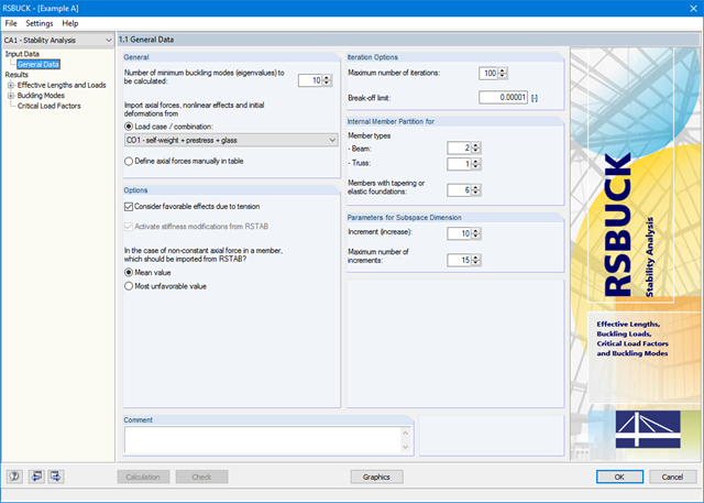
- Member-wise output of effective lengths L about weak and strong axis with corresponding effective length factors β
- Results by member listing standardized buckling modes
- Results of critical load factors regarding buckling case for entire structure
- Graphics and animated visualization of buckling modes on the rendered model
- Identification of members free of compression forces
- Optional transfer of the effective lengths to other RSTAB design modules for equivalent member designs according to standards
- Optional export of buckling mode geometry to the RSIMP add-on module in order to create RSTAB imperfections
- Direct data export to MS Excel
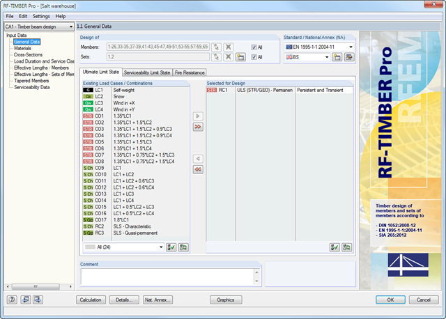
After opening the add-on module, it is necessary to select the members/sets of members, load cases, load or result combinations for the ultimate limit state, serviceability limit state, and fire resistance design. The materials from RFEM/RSTAB are preset and can be adjusted in RF-/TIMBER Pro. Material properties listed in the respective standard are included in the material library.
After the cross-section check, the module determines the load duration classes (LDC) and the service classes (SECL). It is possible to assign them to the selected load cases and members.
Combined cross-sections may consist of various materials. The RF-/TIMBER Pro add-on module performs designs considering the shifted neutral axis (in the case of semi-rigid cross-sections). The deformation analysis requires the reference lengths of the relevant members and sets of members. Furthermore, you can define a specific direction of deflection, precamber and the beam type.
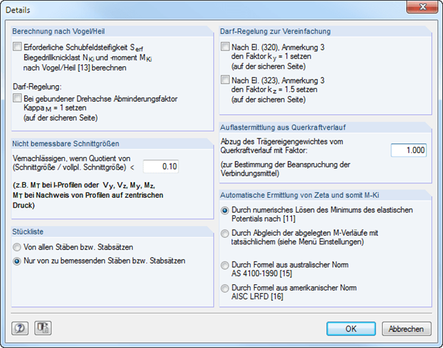
In RF‑/LTB, the design is usually performed according to the equivalent member method according to DIN 18800, Part 2. However, you can specify extensive detailed settings for the design in a separate dialog box:
Design according to Bird/Heil
Optionally, it is possible to apply the method according to Bird/Heil in the program
- the required shear stiffness Sreq
- the lateral-torsional buckling load Nki
- the critical buckling moment Mki
.
This plastic-plastic calculation method is only valid for lateral and torsional restraints with simple bending with simultaneous load introduction on the upper flange. Further requirements that must be met can be found in the program manual. In case of invalid conditions (for example, biaxial bending), RF-/LTB displays the corresponding error message. In addition, the reduction factorκM for the bending moments My can be set to 1.0 if a restrained rotation axis is present.
Non-Designable Internal Forces
It is possible to neglect non-designable internal forces and thus exclude them from the design if the quotient of the internal force and the fully plastic internal force falls below a certain value. This way, you can neglect, for example, a small moment about the minor axis, thus avoiding the method for biaxial bending.
Allowance according to DIN 18800, Part 2, Element (320) and Element (323)
Automatic determination of ζ
If you want the factor for the determination of the ideal elastic critical moment Mcr to be determined automatically, you can select one of the following types:
- Solving the elastic potential numerically
- Comparison of moment diagrams
- Australian Standard AS 4100-1990
- US standard AISC LRFD
When aligning the moment distributions, you can use the library which contains more than 600 moment distributions in tables.
- Determination of longitudinal, shear, and torsional reinforcement
- Representation of minimum and compression reinforcement
- Determination of neutral axis depth, concrete and steel strains
- Design of member sections affected by bending about two axes
- Design of tapered members
- Determination of deformation in state II, for example according to EN 1992-1-1, 7.4.3
- Considering tension stiffening
- Considering creep and shrinkage
- Precise breakdown of reasons for failed design
- Design details of all design locations for better traceability of reinforcement determination
- Options to optimize cross‑sections
- Visualization of concrete section with reinforcement in 3D rendering
- Output of complete steel schedule
- Fire resistance design according to the simplified method (zone method) according to EN 1992‑1‑2 for rectangular and circular cross‑sections
- Optional extension of the RF‑CONCRETE Members add‑on module with a nonlinear calculation of frameworks for the ultimate and serviceability limit states. The extension enables the design of potentially unstable structural components by means of a nonlinear calculation, or a nonlinear deformation analysis of 3D frameworks. Find more information under the product description of the RF-CONCRETE NL add‑on module.
- Design of tension, compression, bending, shear, and combined internal forces
- Stability analysis for flexural buckling and lateral-torsional buckling
- Automatic determination of stability factors according to Annexes E, F, and G
- Optional application of discrete lateral supports to beams
- Automatic slenderness check of cross-section parts under compression
- Deformation analysis (serviceability)
- Cross-section optimization
- Wide range of cross-sections available, such as rolled I-sections, channel sections, rectangular hollow sections, angles, T-sections. Welded sections: I-shaped (symmetrical and asymmetrical about major axis), channel sections (symmetrical about major axis), rectangular hollow sections (symmetrical and asymmetrical about major axis), angles, round pipes, and round bars
- Clearly arranged result tables
- Detailed result documentation including references to design equations of the used standard
- Various filter and sorting options of results, including result lists by member, cross-sections, x-location, or by load case, load and result combination
- Result table of member slenderness and governing internal forces
- Parts list with weight and solid specifications
- Seamless integration in RFEM/RSTAB
- Design of tension, compression, bending, shear, and combined internal forces
- Stability analysis for flexural buckling and lateral-torsional buckling
- Automatic determination of critical buckling loads and overall stability factors for lateral-torsional buckling according to Annex B
- Optional application of discrete lateral supports to beams
- Automatic local stability analysis and check of plastic design criteria of a cross-section
- Deformation analysis (serviceability)
- Cross-section optimization
- Wide range of cross-sections available, such as rolled I-sections, channel sections, rectangular hollow sections, angles, T-sections. Welded sections: I-shaped (symmetrical and asymmetrical about major axis), channel sections (symmetrical about major axis), rectangular hollow sections (symmetrical and asymmetrical about major axis), angles, round pipes, and round bars
- Clearly arranged result tables
- Detailed result documentation including references to design equations of the used standard
- Various filter and sorting options of results, including result lists by member, cross-sections, x-location, or by load case, load and result combination
- Result table of member slenderness and governing internal forces
- Parts list with weight and solid specifications
- Seamless integration in RFEM/RSTAB
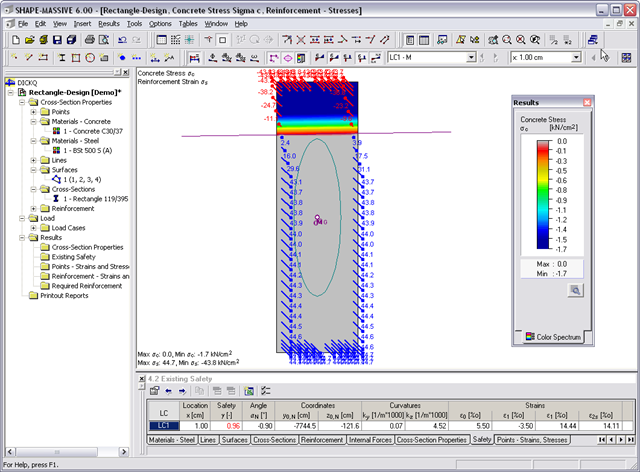
- Stresses σ and strains ε of concrete and reinforcement without considering concrete tensile strength (state II)
- Ultimate limit state design (existing safety) or design of defined internal forces
- Location of the neutral axis α0, y0,N, z0,N
- Curvatures ky, kz
- strain in the zero point ε0 and governing strains at the compression edge ε1 and at the tension edge ε2
- Governing steel strain ε2s
- Design of tension, compression, bending, shear, combined internal forces, and torsion
- Stability analysis for flexural buckling, torsional buckling, and lateral-torsional buckling
- Optional application of discrete lateral supports to beams
- Deformation analysis (serviceability)
- Cross-section optimization
- Wide range of cross-sections available, such as rolled I-sections, channel sections, rectangular hollow sections, angles, T-sections. Welded sections: I-shaped (symmetrical and asymmetrical about major axis), channel sections (symmetrical about major axis), rectangular hollow sections (symmetrical and asymmetrical about major axis), angles, round pipes, and round bars
- Clearly arranged result tables
- Detailed result documentation including references to design equations of the used standard
- Various filter and sorting options of results, including result lists by member, cross-sections, x-location, or by load case, load and result combination
- Result table of member slenderness and governing internal forces
- Parts list with weight and solid specifications
- Seamless integration in RFEM/RSTAB